Human Head Retopology with Wrap 3D: Create Game-Ready Models
Discover how to easily improve character detail and make models that are equipped for gaming using a special head retopology technique with the Wrap 3D program.
Realistic character modeling, UV mapping, expressions, and displacement mapping are covered in this tutorial.
Workflow: Head Retopology with Wrap 3D
A Dive into Wrap 3D Techniques
- This software will help us fix our sculptures’ topology, and we will be able to add ZBrush Layers.
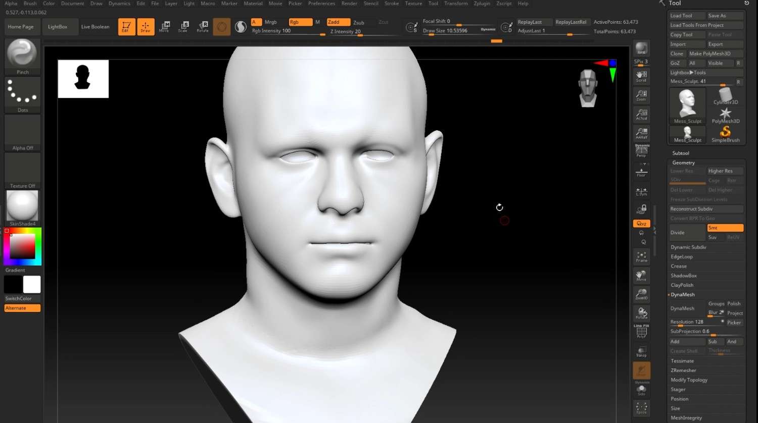
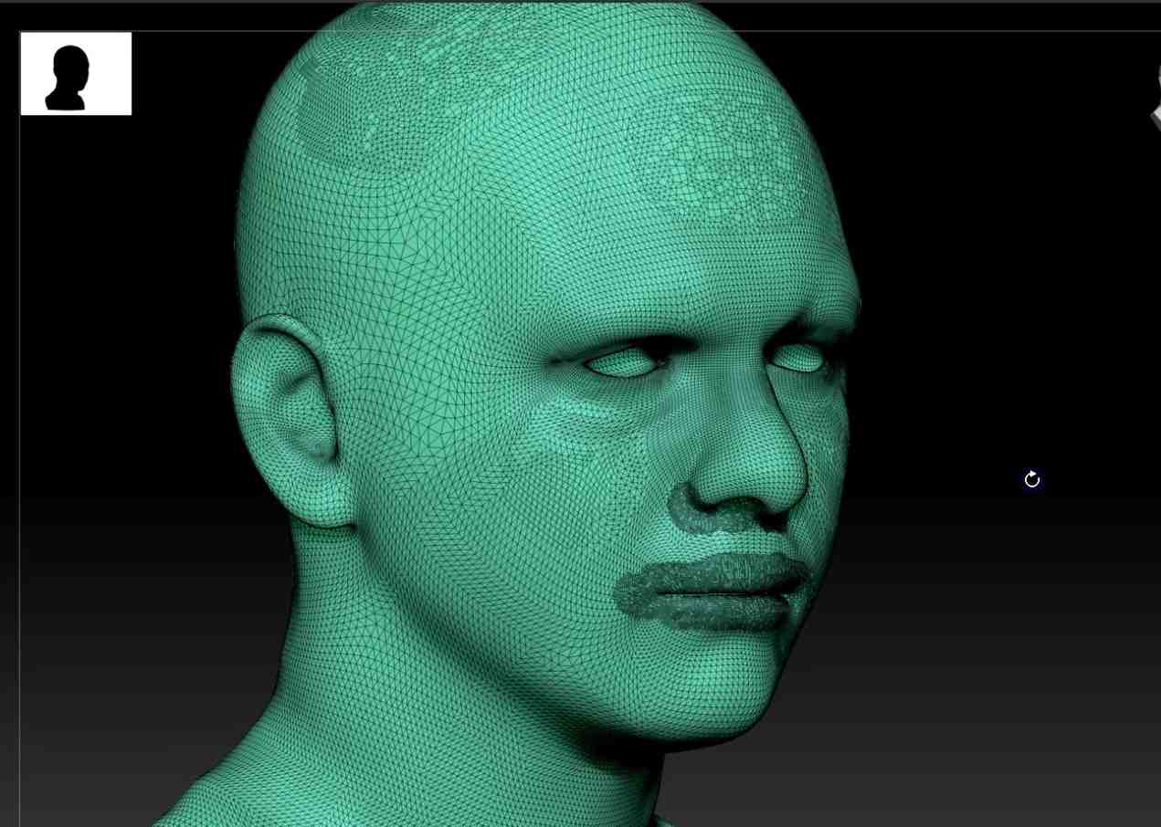
- Because of its Decimated topology, the sculpt used in this tutorial isn’t suitable for any game or cinematic use.
- Export the sculpt as an OBJ file from ZBrush, as this format is required for Wrap 3D to function.
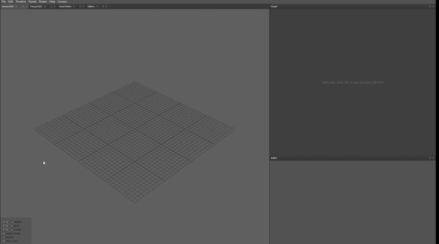
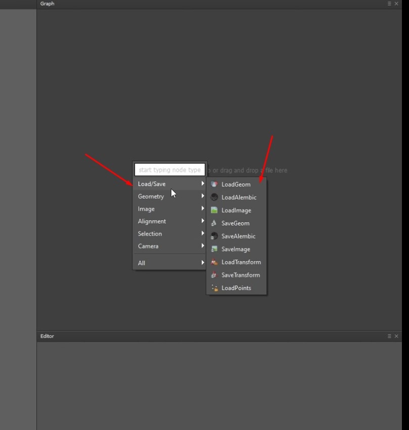
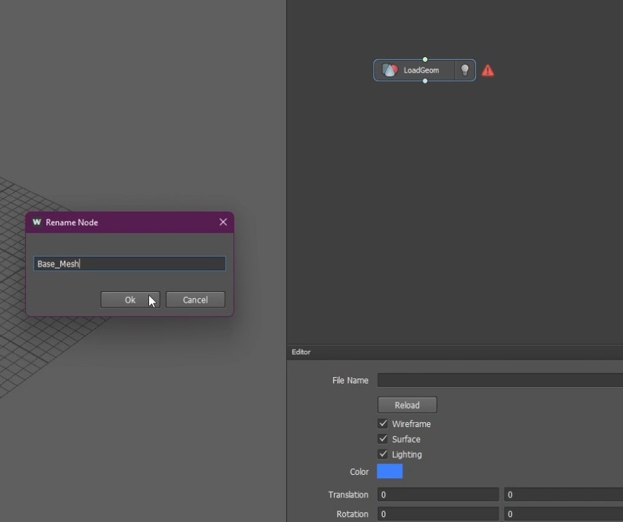
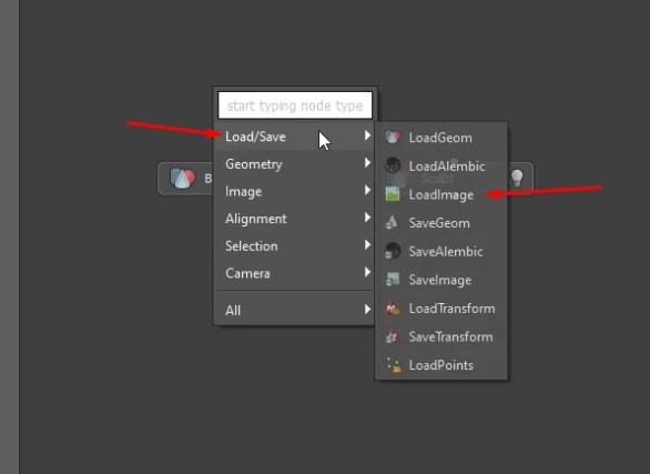
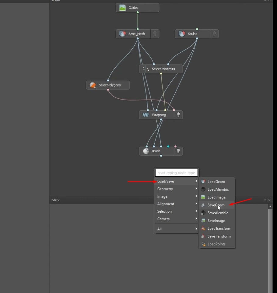
- Click the Tab key in the Graph on the right side of the workspace.
- Select LoadGeom by hovering over the Load/Save options.
- A node will be created that can be renamed by clicking F2.
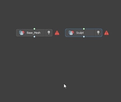
- Rename the first node to Base_Mesh.
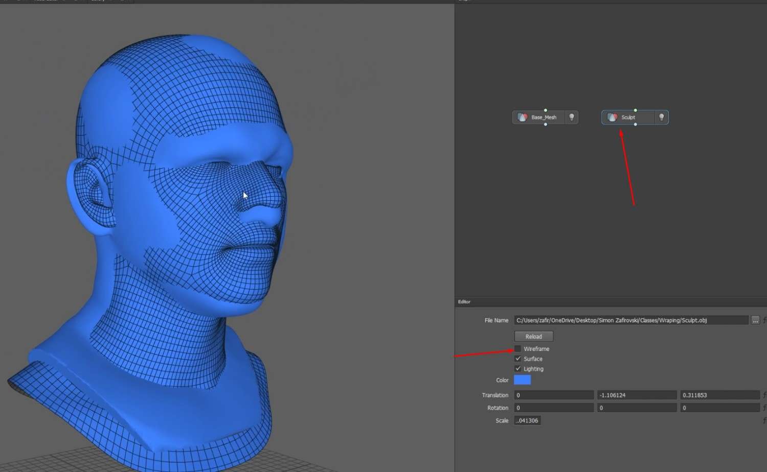
- Make another LoadGeom and name it Sculpt.
Aligning the Sculpt and Base Mesh in Wrap 3D
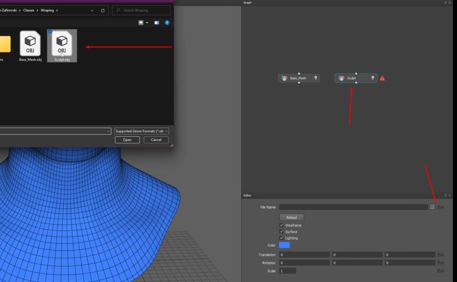
- Click on the Base_Mesh node and select the Base_Mesh OBJ file for it.
- In the Sculpt node, select the Sculpt OBJ.
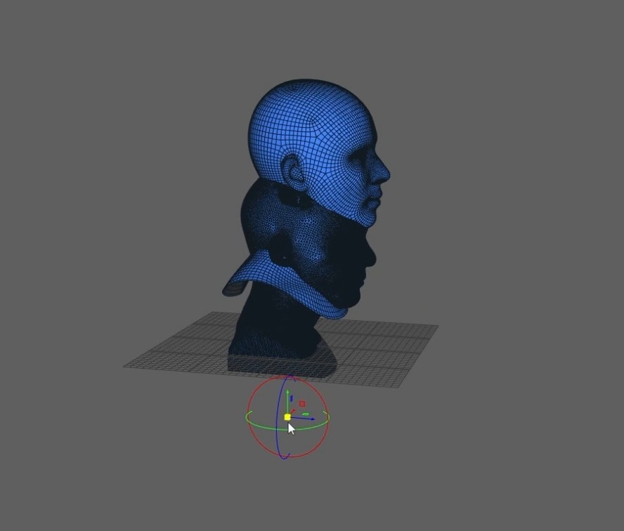
- If the sculpt model is too small or not completely aligning with the Base_Mesh, just like in Autodesk Maya, scale and move the sculpt to align with the Base_Mesh.
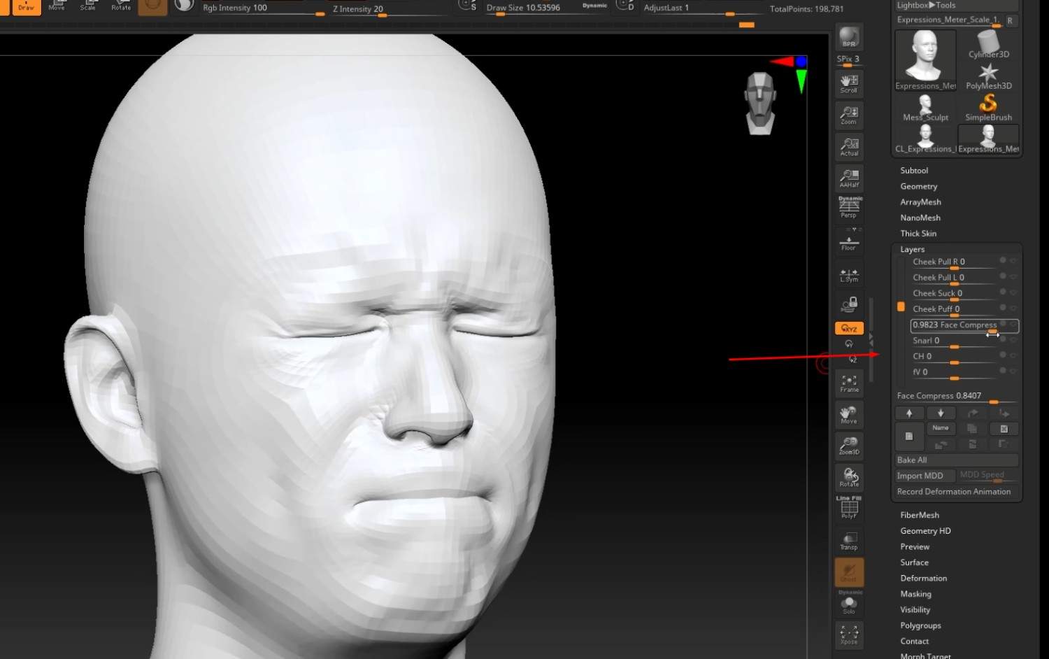
- You can use UV maps and layers on the Base_Mesh to create various expressions.
- Uncheck the Wireframe box to disable the topology on the sculpt and Base_Mesh.
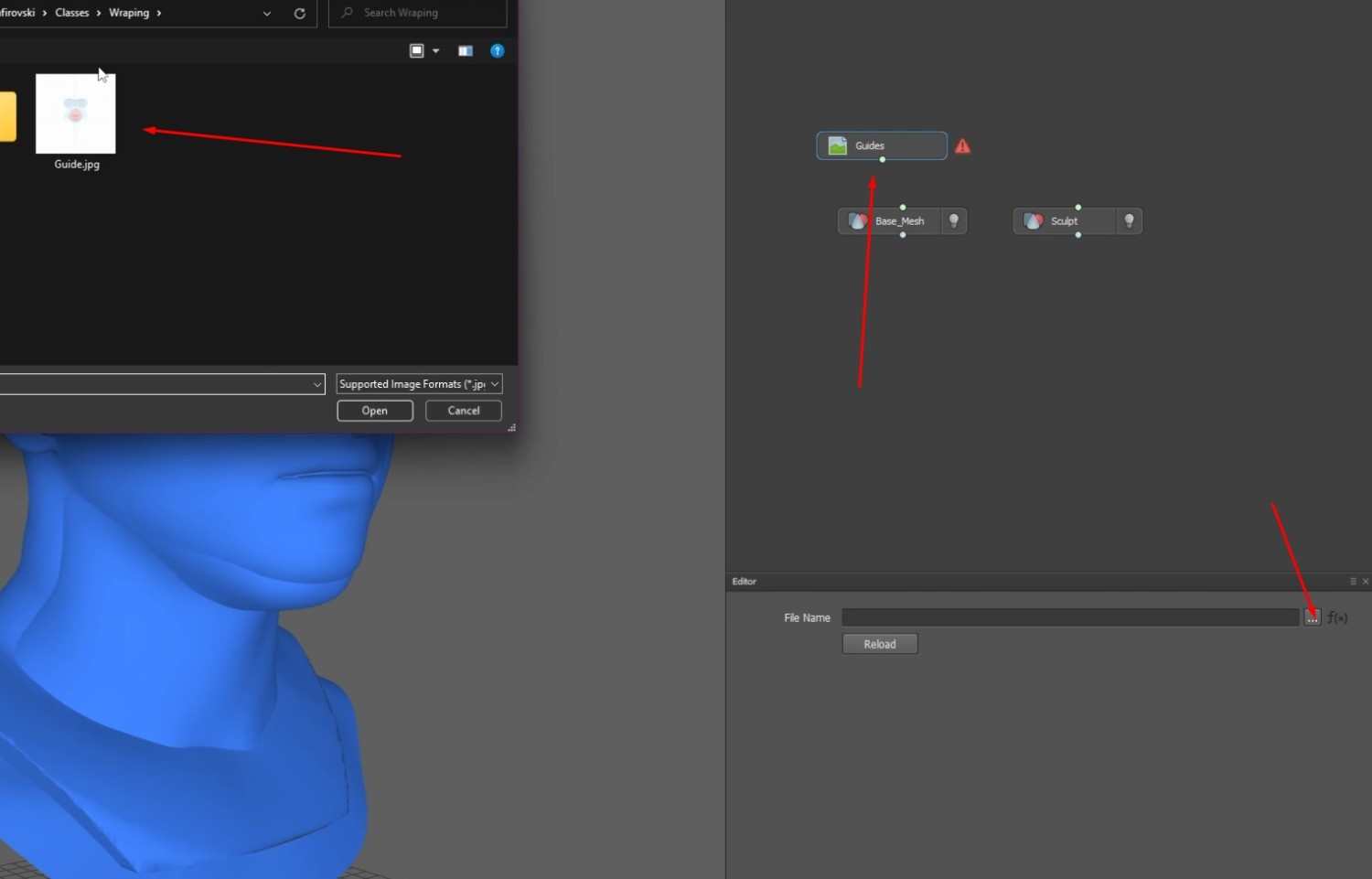
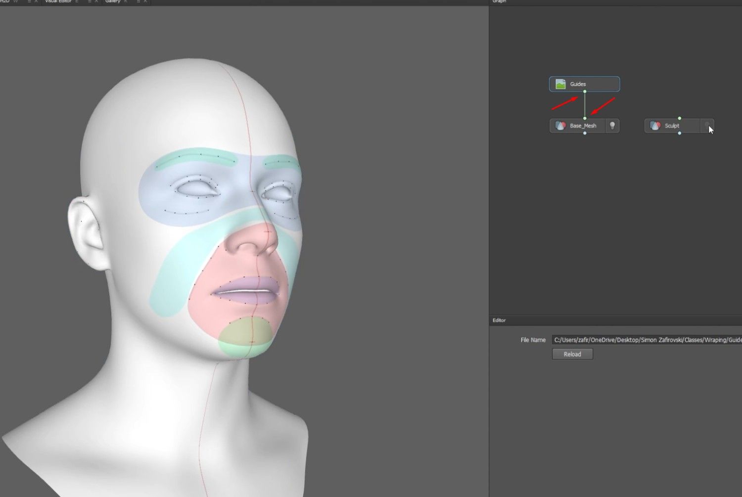
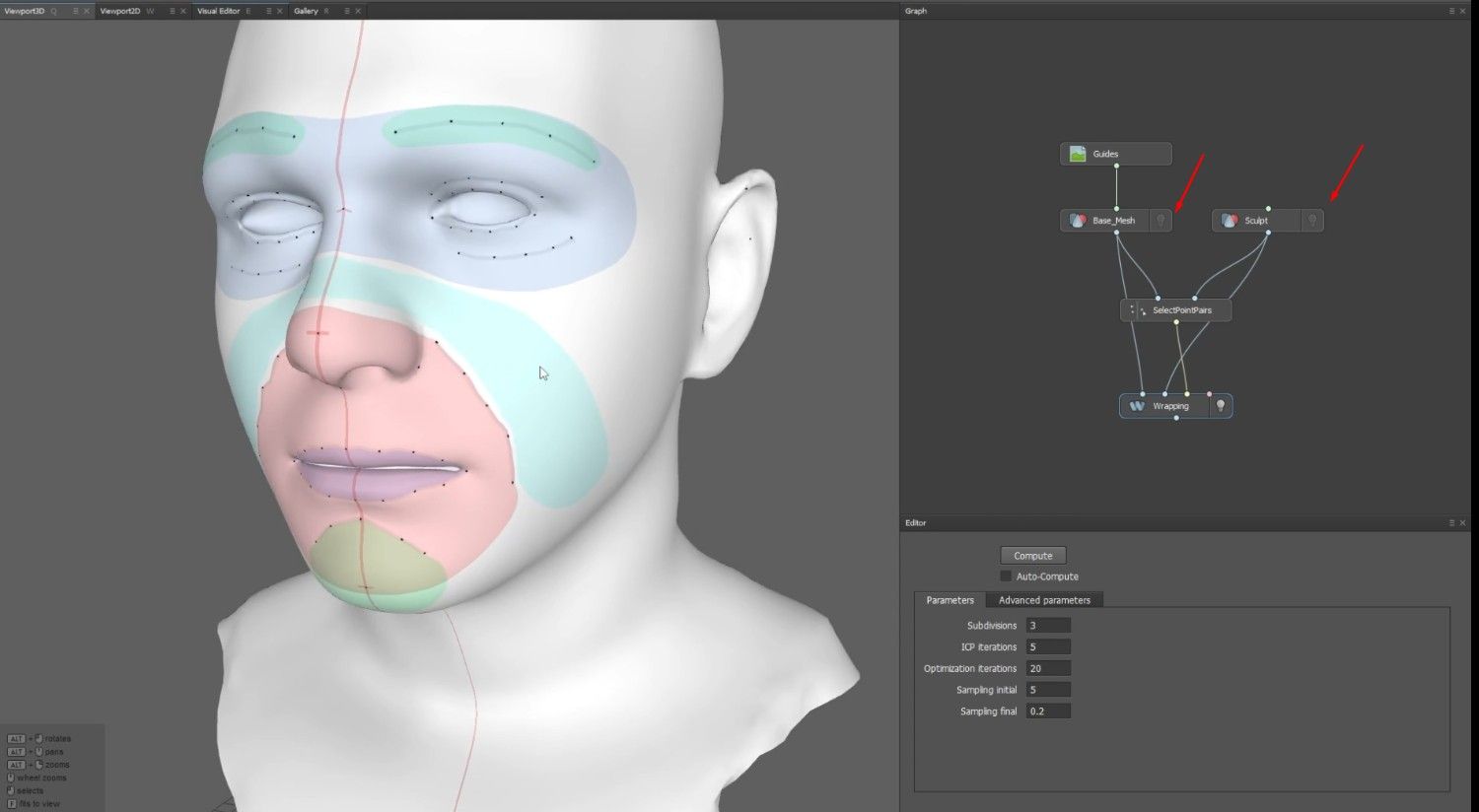
- In the Graph, add a LoadImage node.
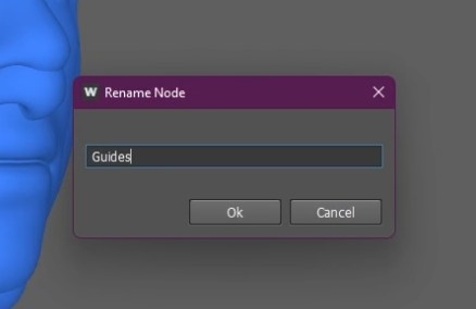
- Rename that node to Guides.
- To add the Guide.jpg image, click the node.
- Connect the image node with the Base_Mesh node by connecting the dots.
Adding Points and Wrapping Process
- The Base_Mesh contains the correct UVs, so loading the image guide won’t be a problem.
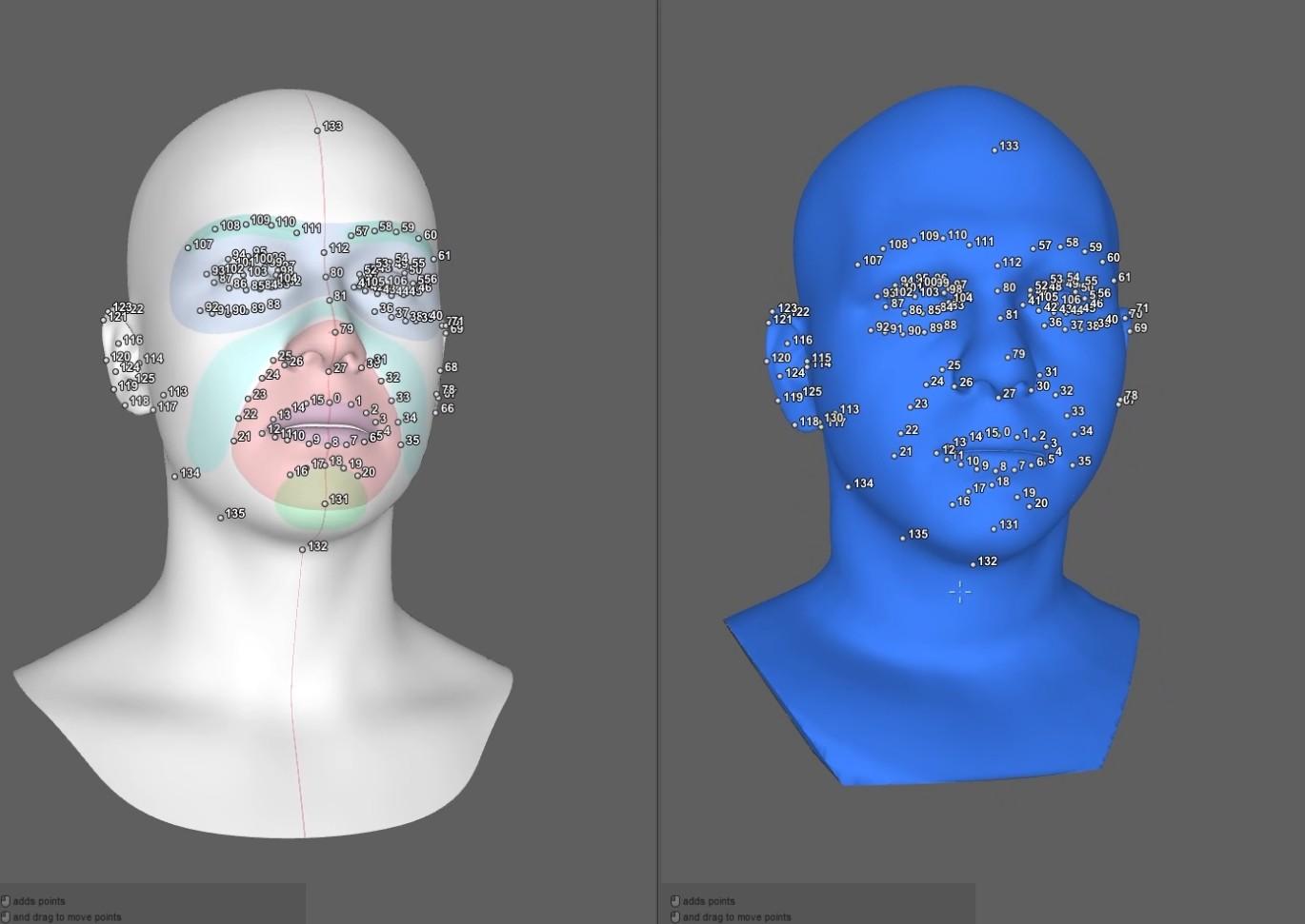
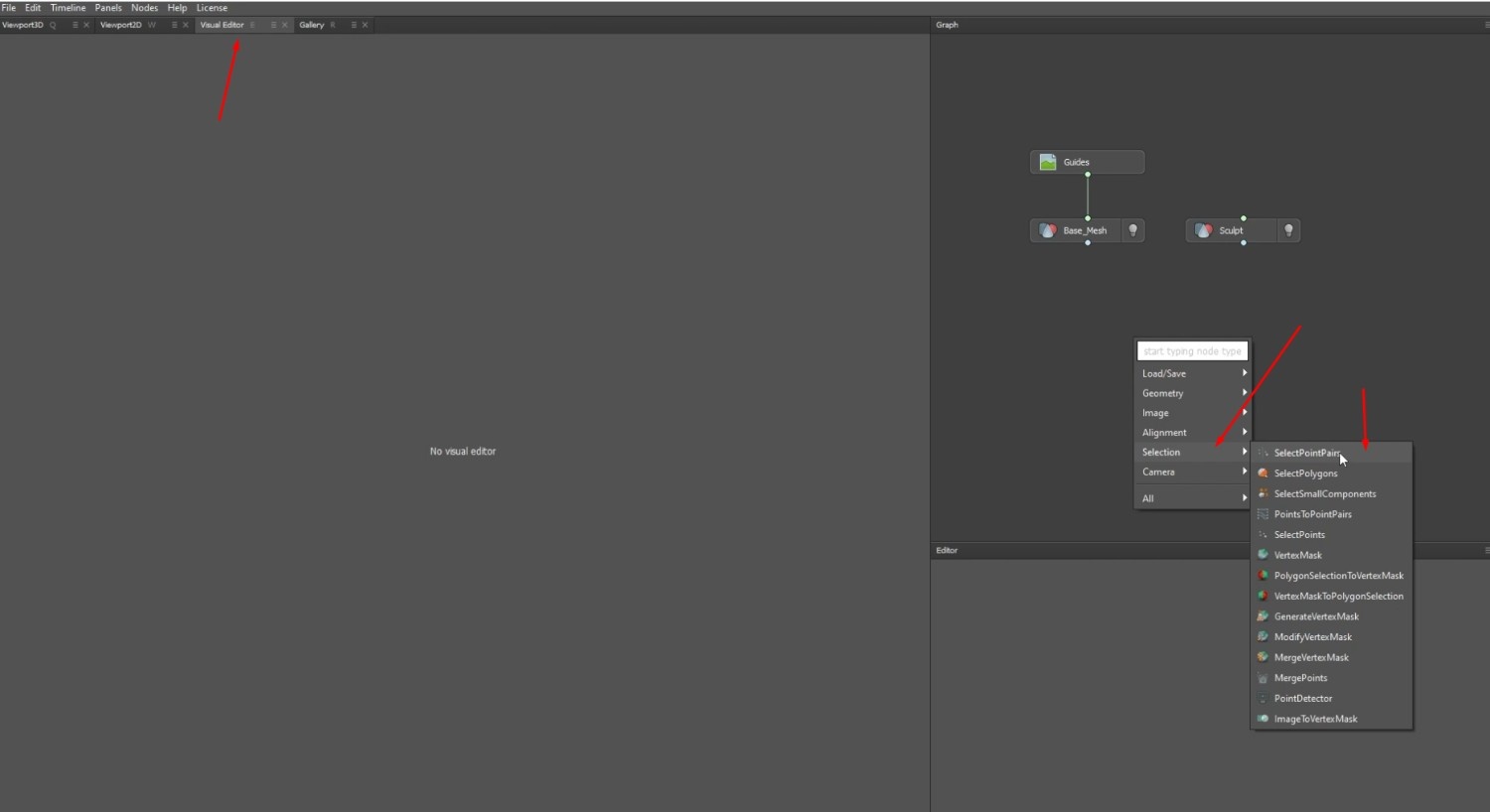
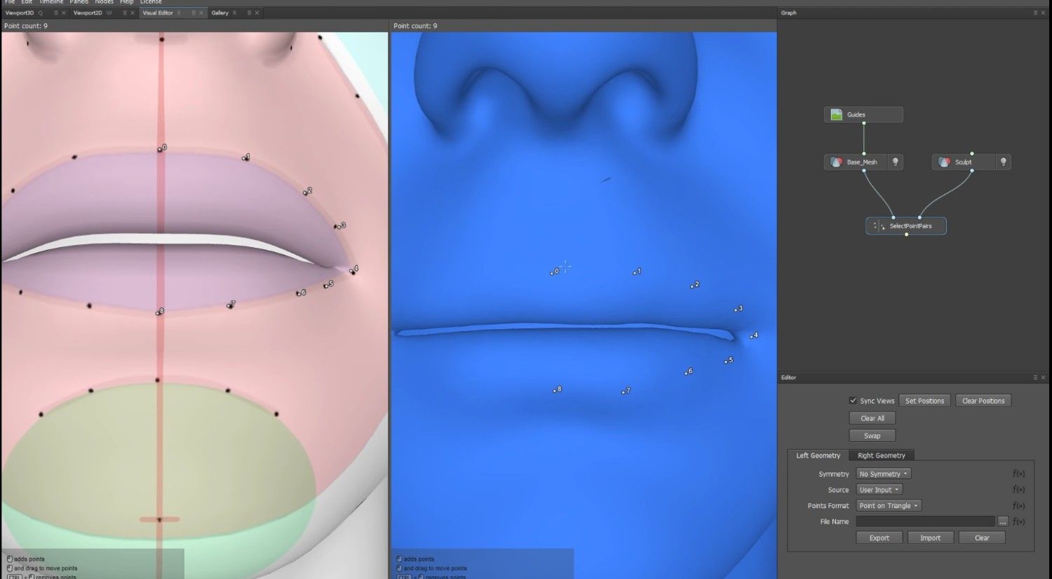
- To add a SelectionPointPairs, click the Visual Editor tab and select the Selection option.
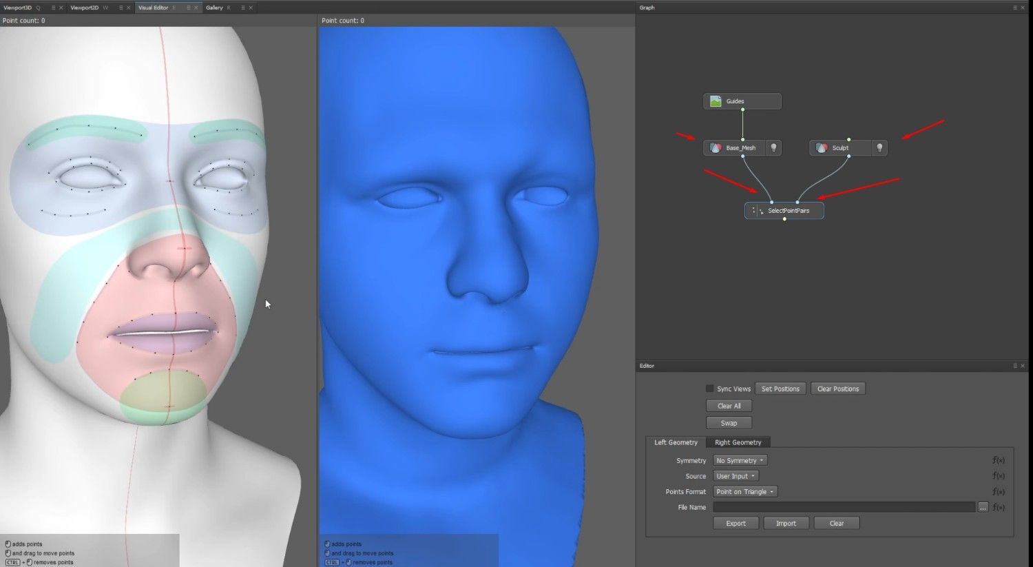
- Connect the node’s left side to the Base_Mesh and its right side to the Sculpt.
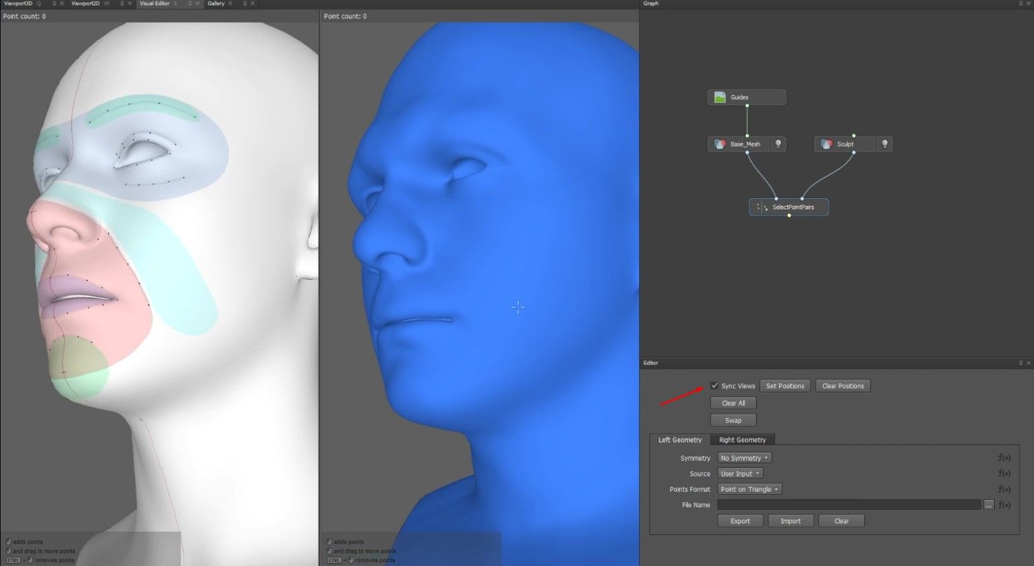
- Enable Syn Views in the Editor window below the Graph.
- This will make it so that if one view is moved, the view next to it will move as well.
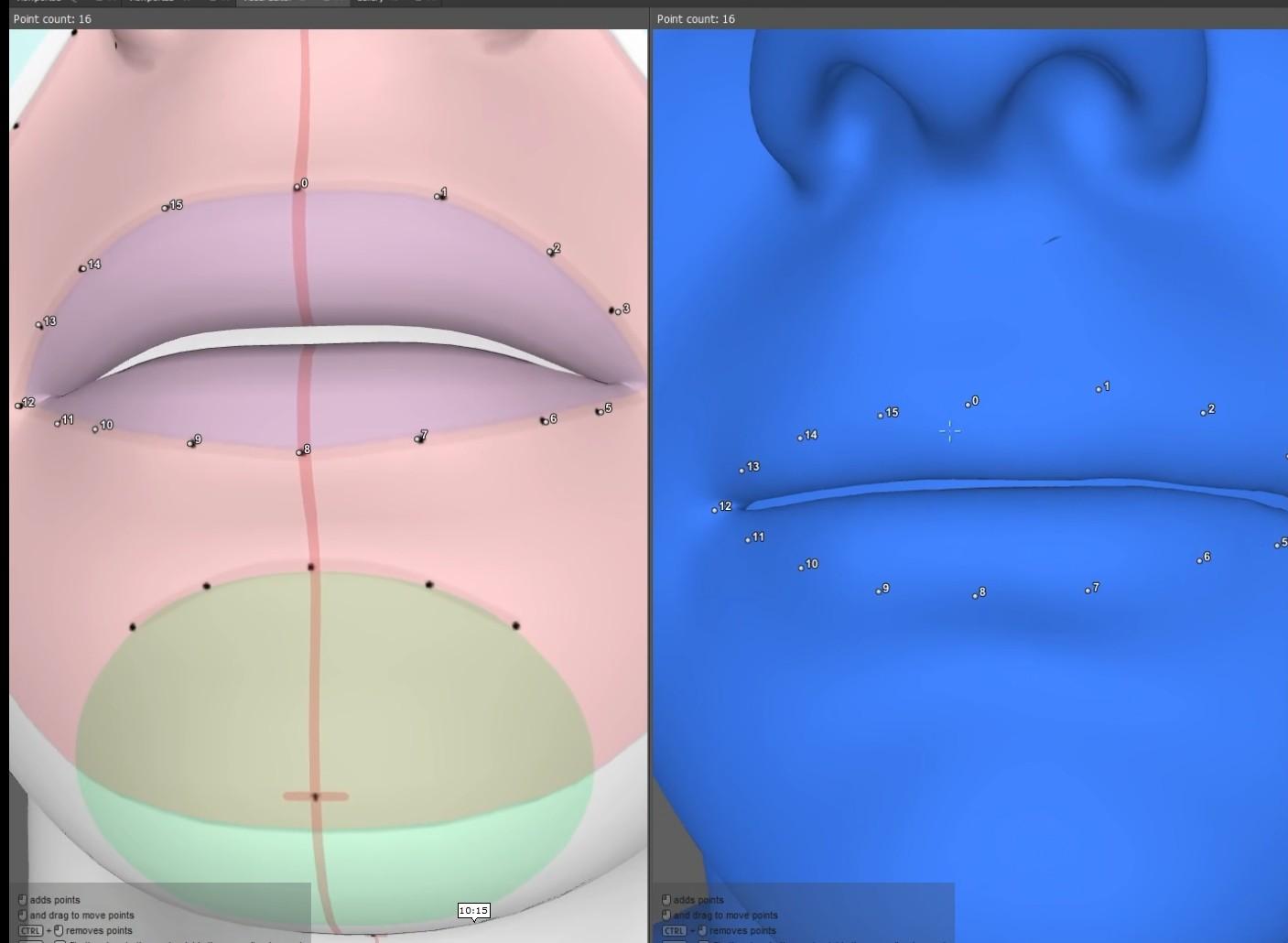
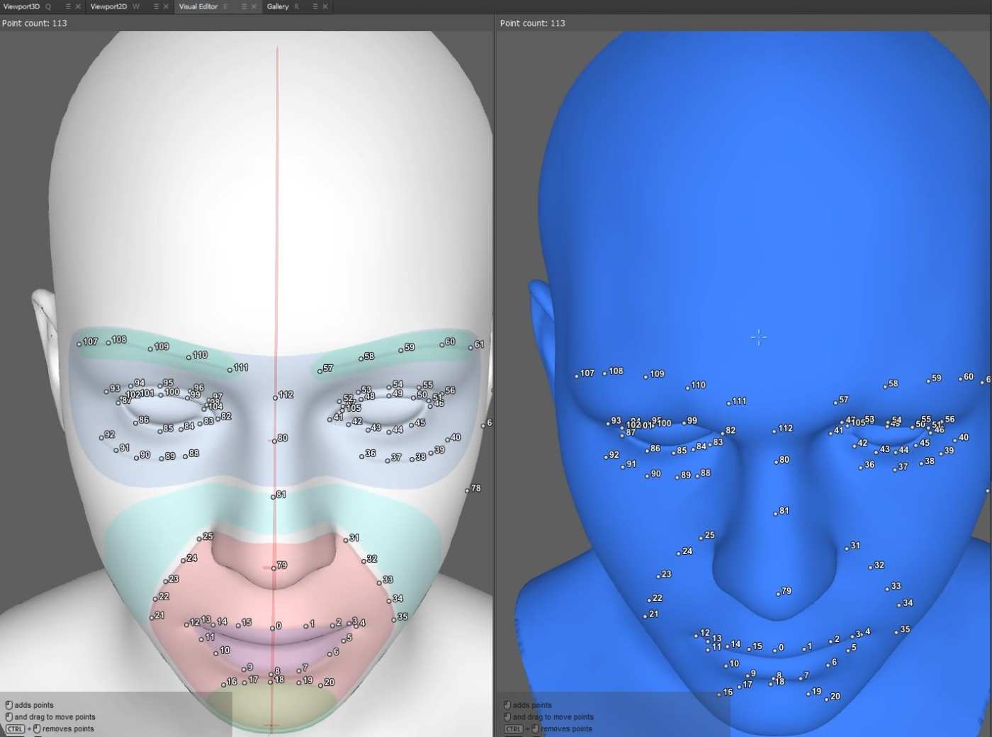
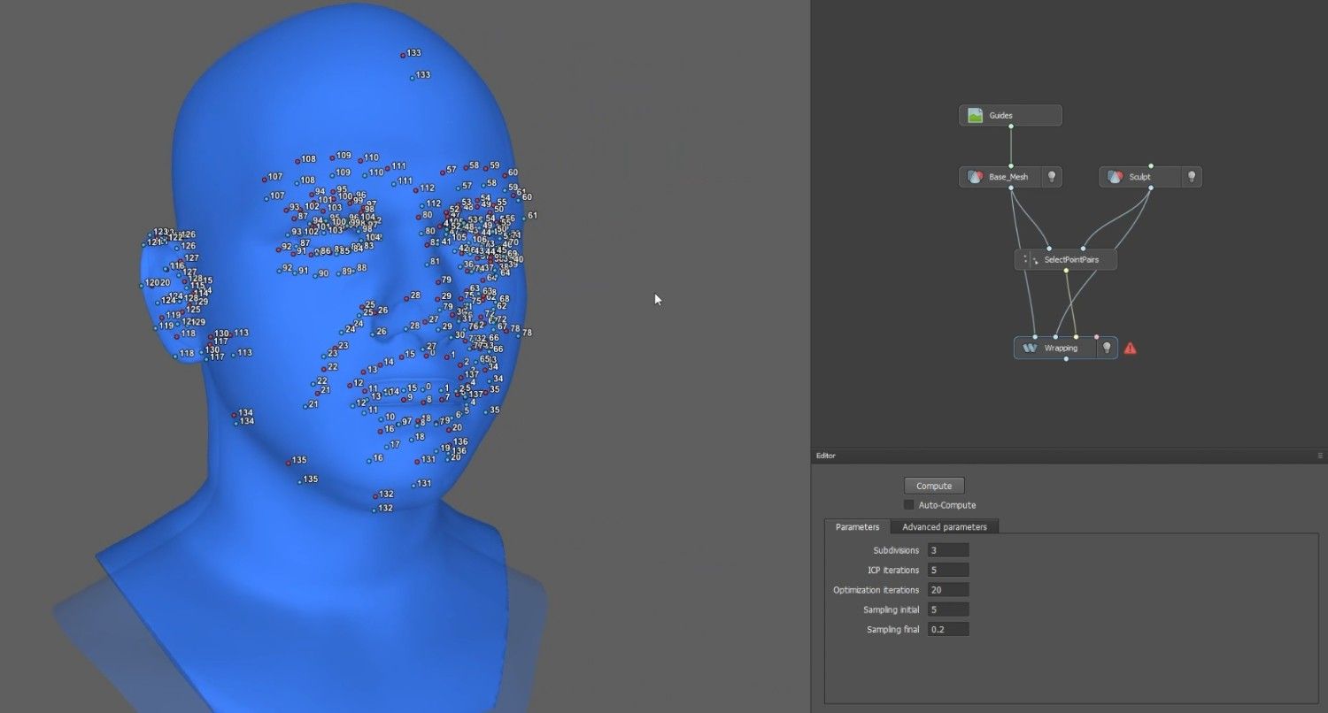
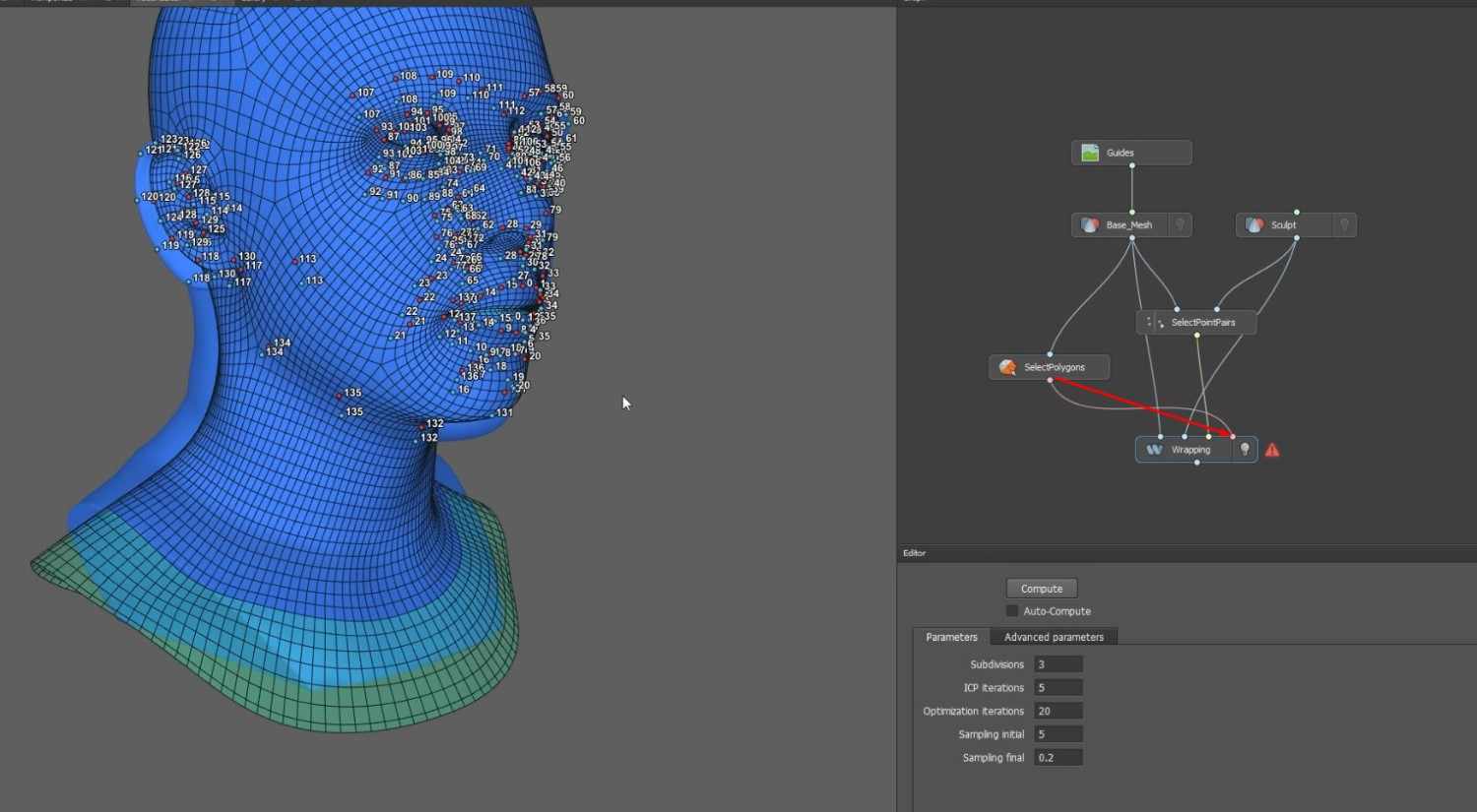
- Place the dots on the Base_Mesh, following the image guide, then repeat the process for the Sculpt in the same order.
- This is important for the UVs to wrap correctly onto the Sculpt afterward.
- Click and drag a dot to reposition it wherever necessary.
Fixing Deformities and Saving the Wrapped Model
- Once the entire face is completed, add the dots to the remaining guides.
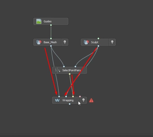
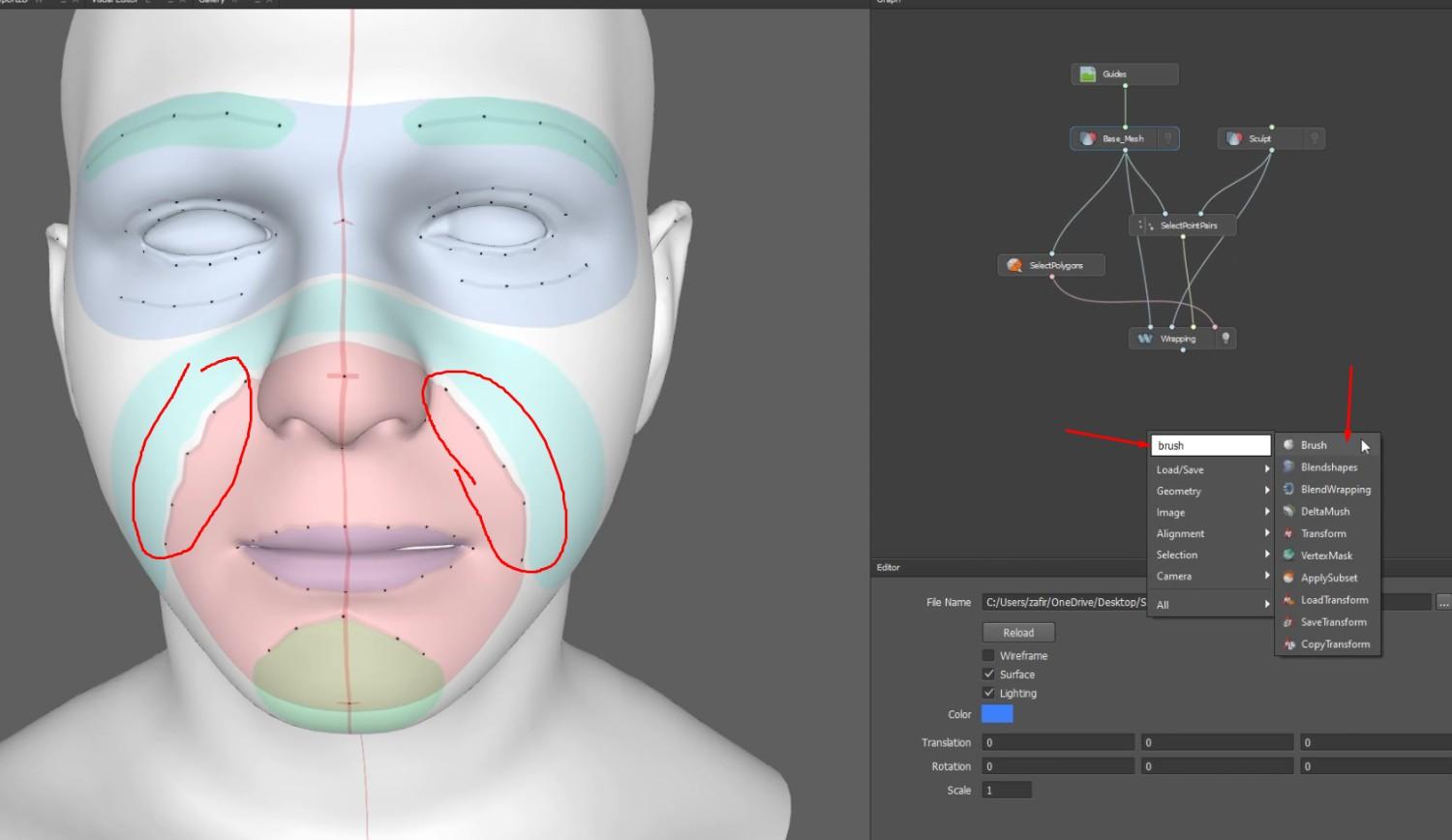
- In the Graph, click the tab and type in “wrap” to find the Wrapping node.
- Connect the wrapping node with the SelectionPointPairs, Sculpt, and Base_Mesh nodes.
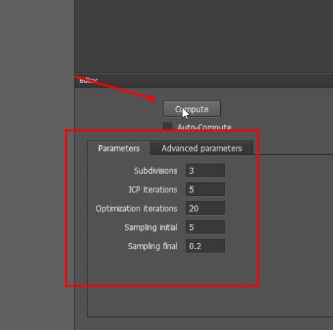
- In the wrapping node, make sure the Parameter settings are set up properly.
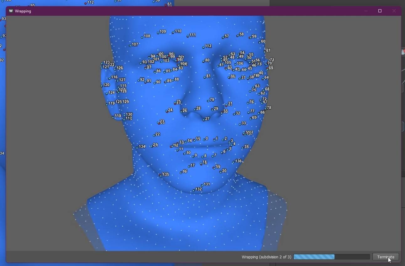
- When everything is set, select the Compute button and wait for the wrapping to finish.
- Return to the Viewport3d window by clicking.
- Once it’s finished, hide the Base_Mesh and Sculpt nodes by clicking the lightbulb icon next to each node.
Importing into ZBrush and Applying Textures
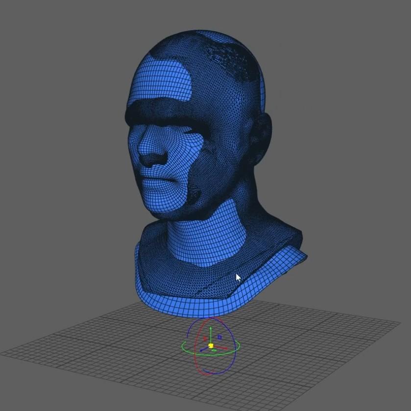
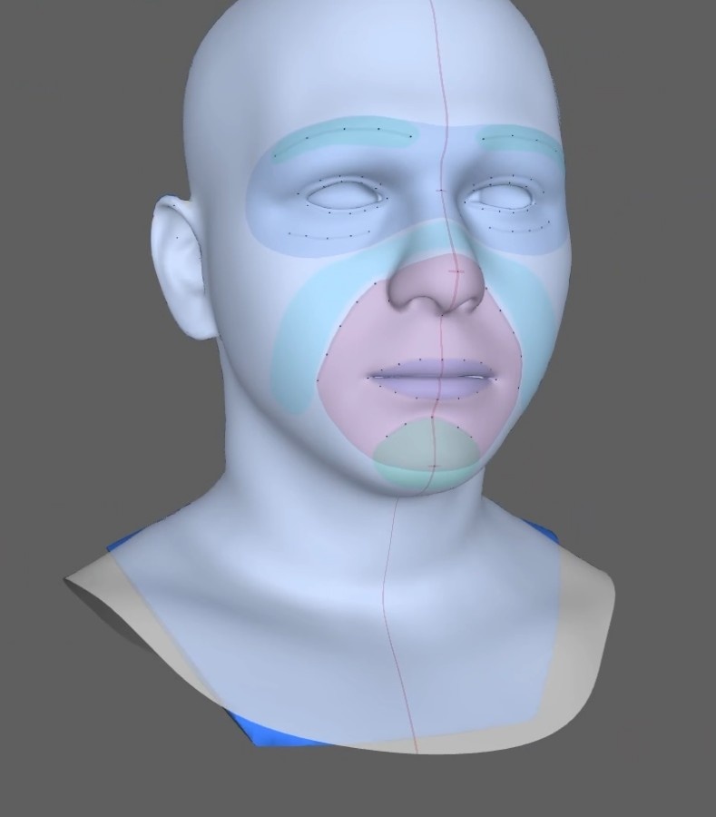
- While the wrapping node is selected, you can see how well the Sculpt was wrapped from the Base_Mesh UV.
- There are deformities around the ends of the Sculpt as well, and the lines around the guides are wiggly instead of perfectly curved.
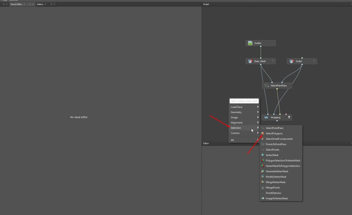
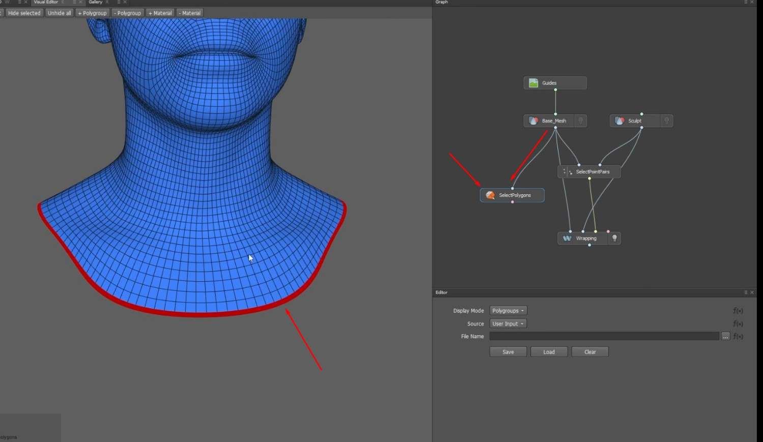
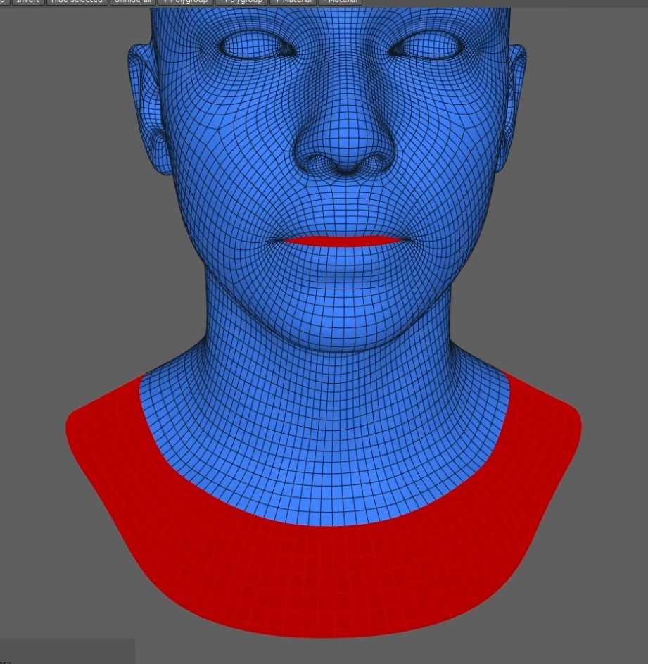
- Return to the View Editor and add a SelectionPolygons node to the graph via the selection tab to fix the ends of the sculpt.
- Connect the SelectionPolygons node with the Base_Mesh node.
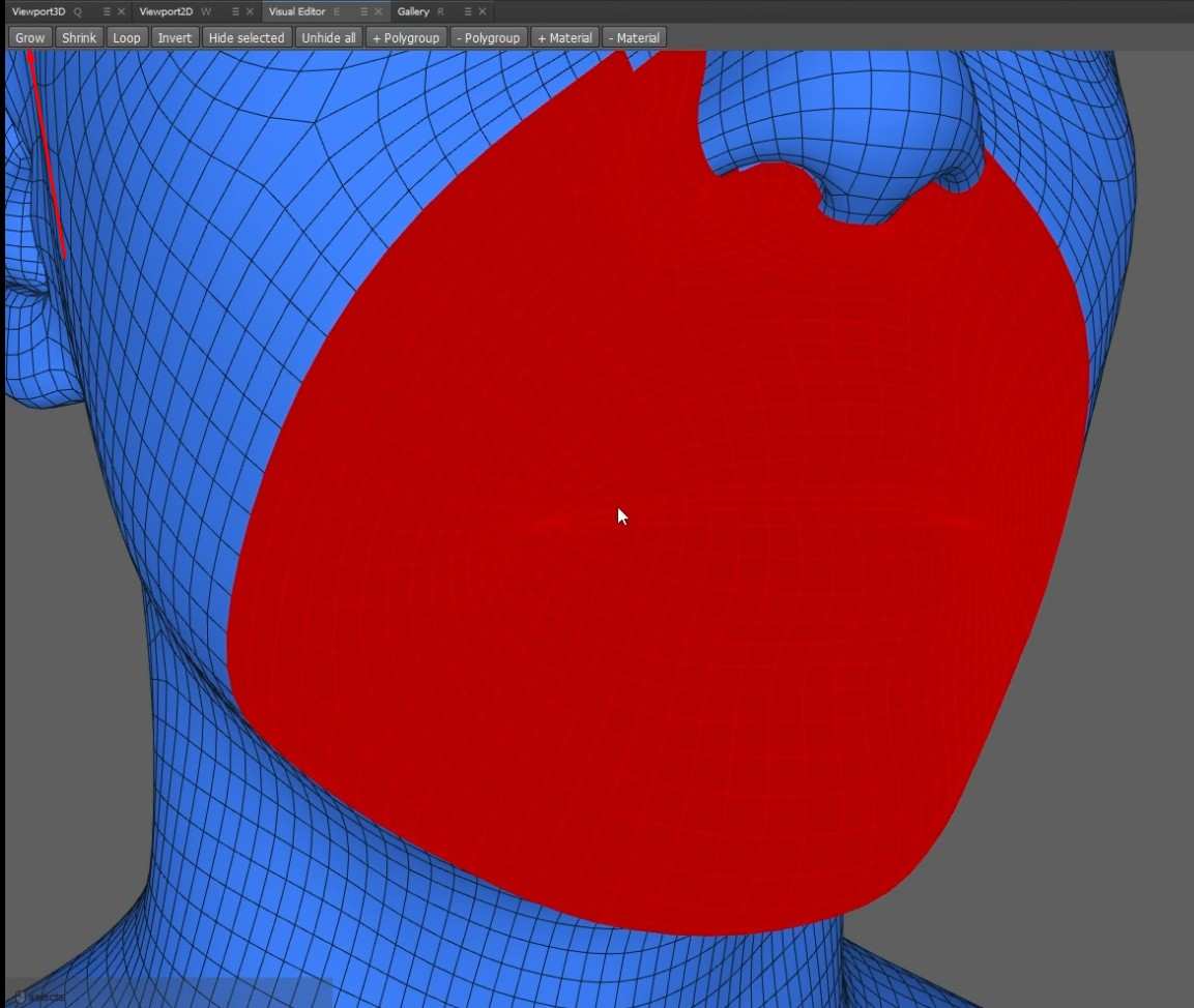
- After connecting, you can use the Shift double-click to do a loop selection to pick certain parts of the polygon from the Base_Mesh, much like you can in Autodesk Maya.
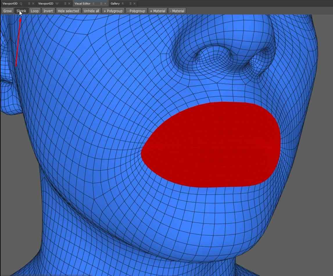
- Also, there is a Grow tool that expands the selection by one.
- If there is too much selected, you can use the Shrink Tool to shrink down the selection by one.
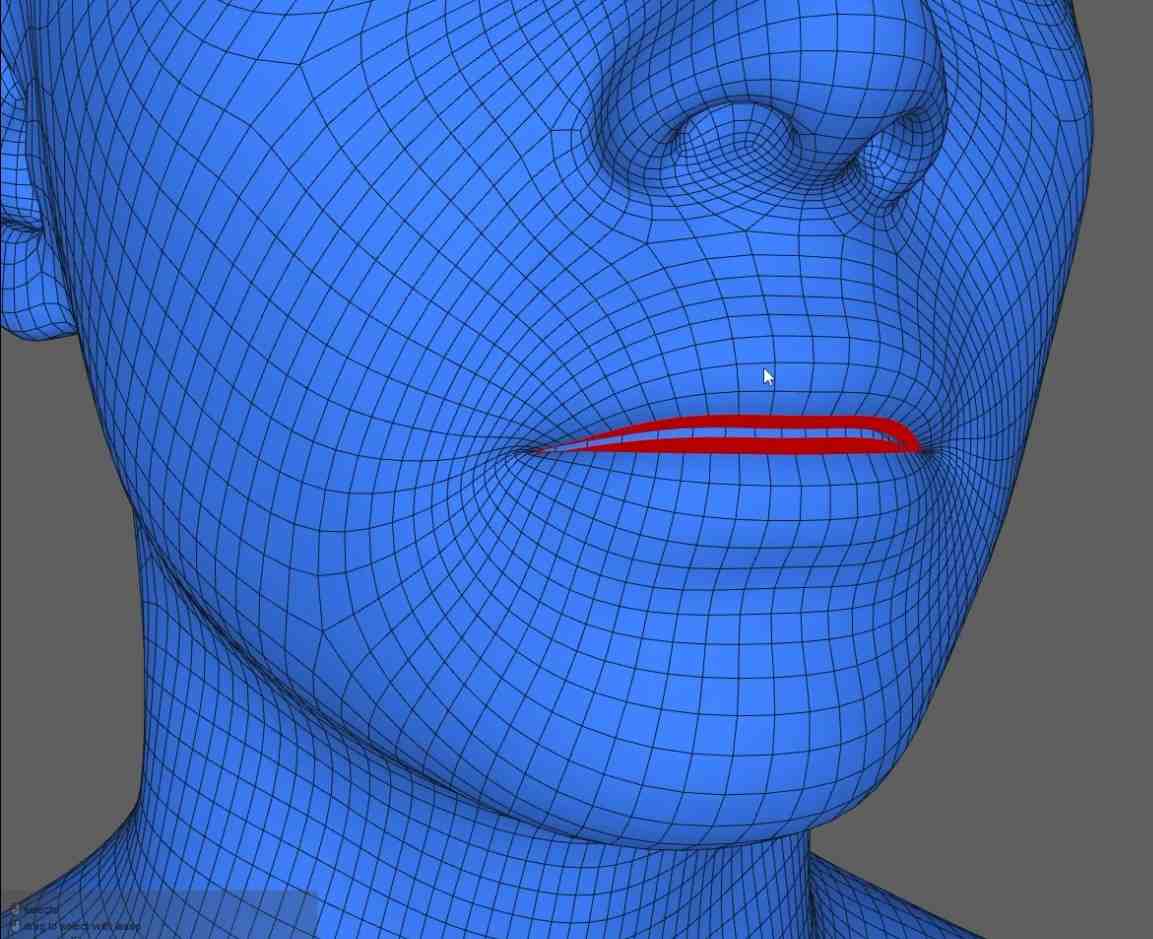
- Select parts of the ends of the neck and the inside of the mouth.
- Connect the SelectionPolygons node to the Wrapping node, then click Compute again.
Adjusting Guides and Saving Geometry
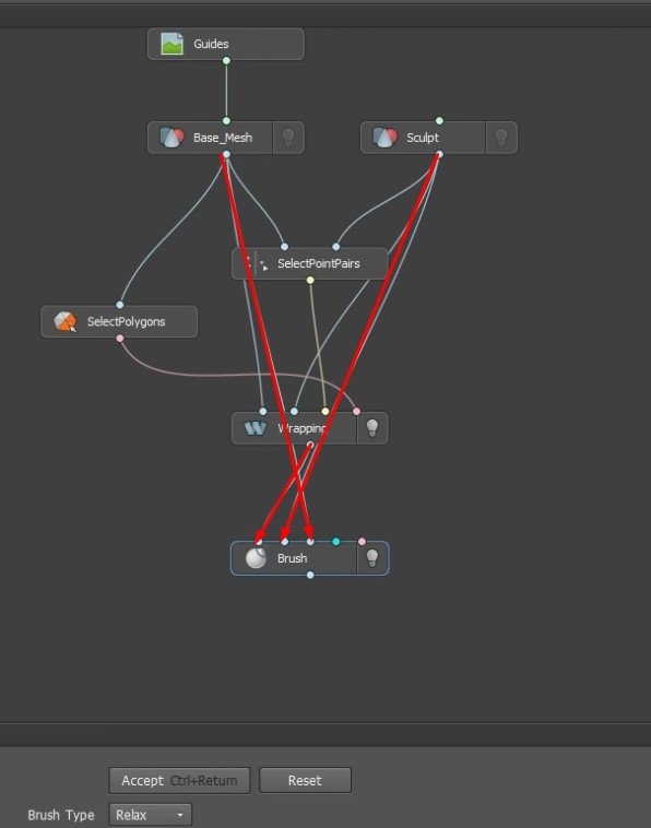
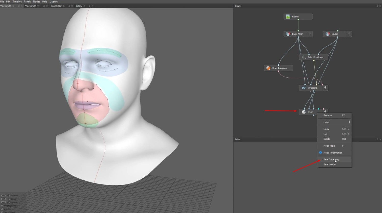
- Add a Brush node inside the graph and attach it to the Base_Mesh, wrapping, and Sculpt nodes to repair the wiggly lines surrounding the guides.
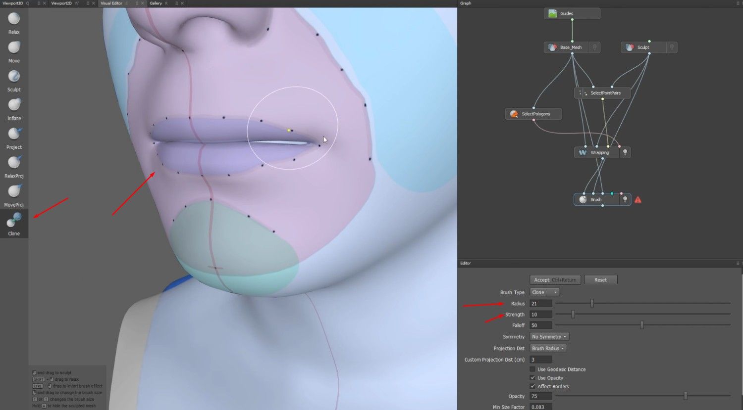
- Select the Clone brush, adjust the Radius and Strength of the brush, then lightly click on the guides to straighten them out.
- Apply this to the entire face.
- Once you have finished using the brush, press the Accept button.
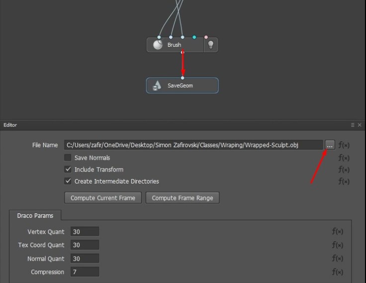
- Add another node in the graph called the SaveGeom node and connect it to the Brush node.
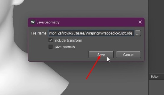
- Name the file, select a location on your desktop, right-click the Brush node, and save the geometry as an OBJ file
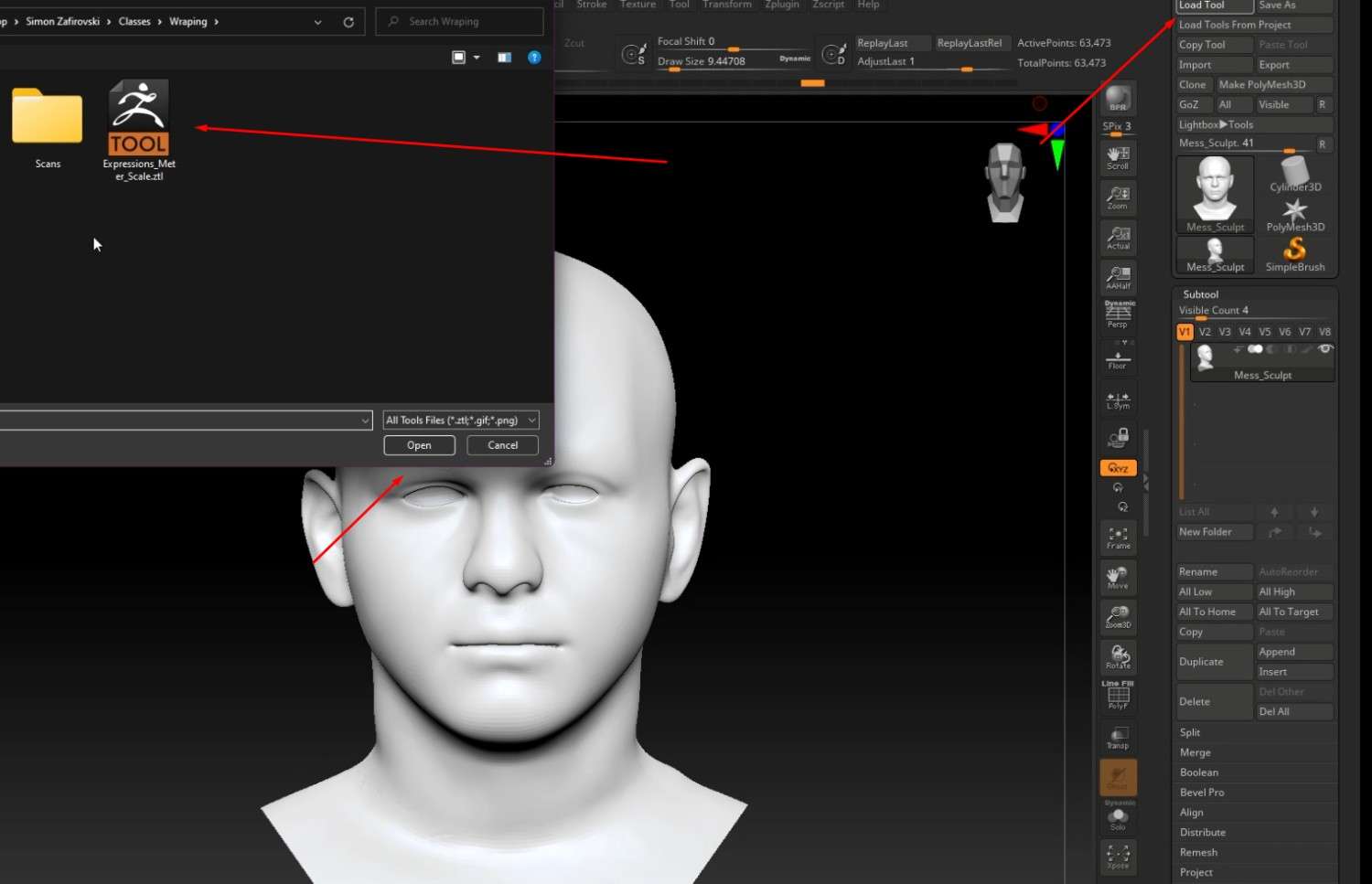
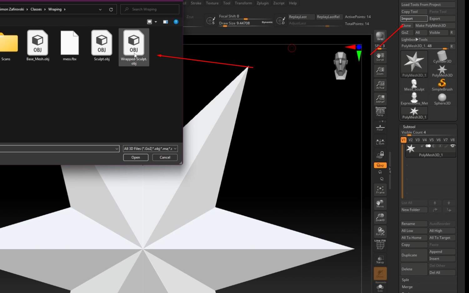
- In Zbrush, import the ZTL file provided for the class, and make sure that it is set to the lowest division before the next step.
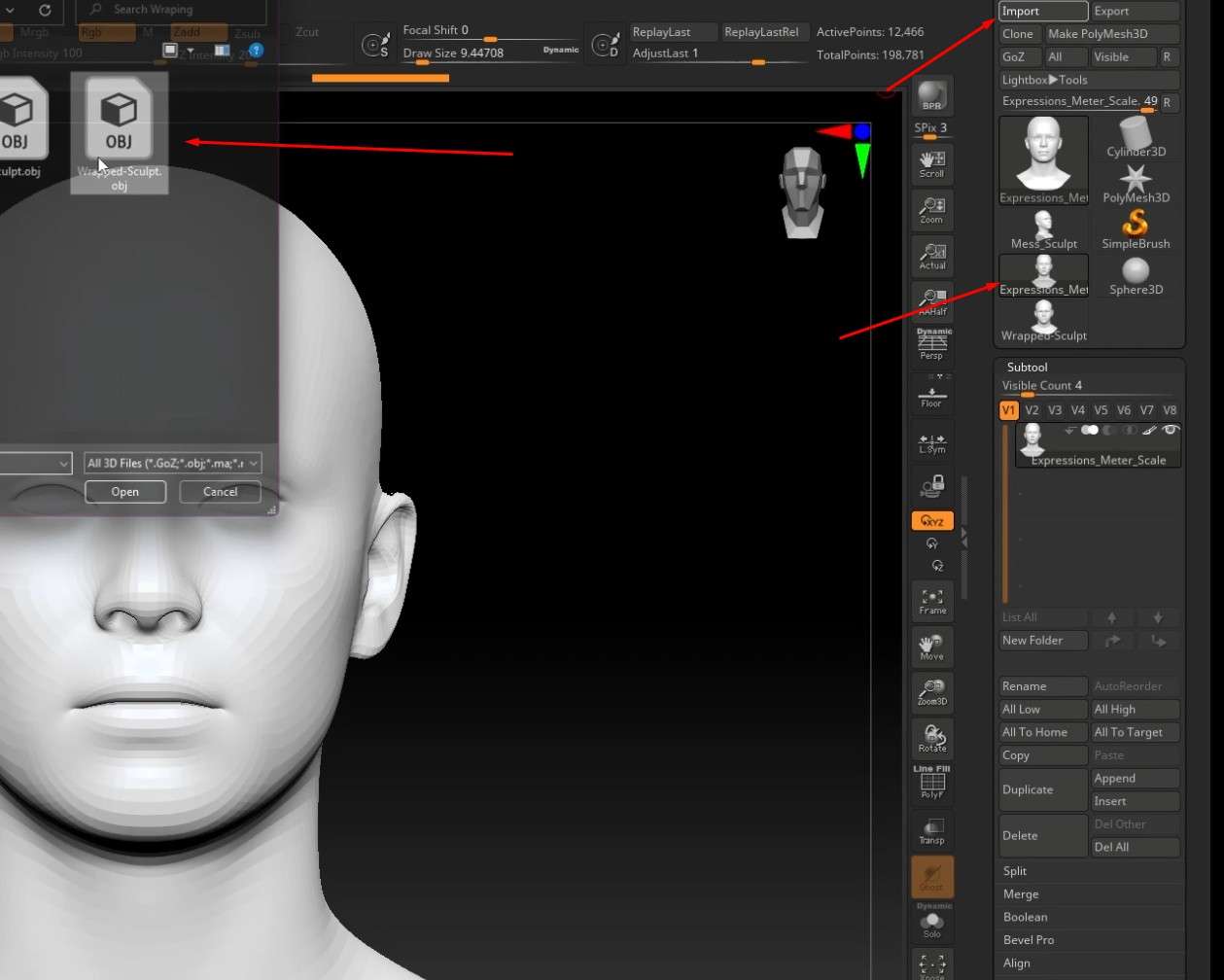
- Next, import the previously saved wrapped 3D file.
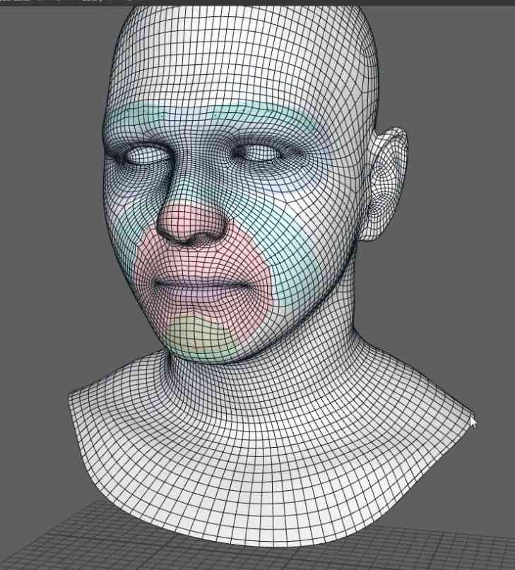
- Once it is imported, the Base_Mesh from the ZTL file will transform to look like the Sculpt because of the placed vertices.
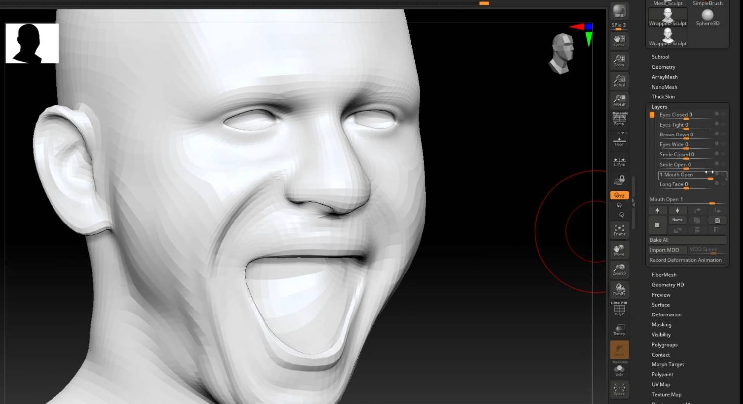
- All of the Base_Mesh’s UV map and Zbrush levels will be available for the Sculp.
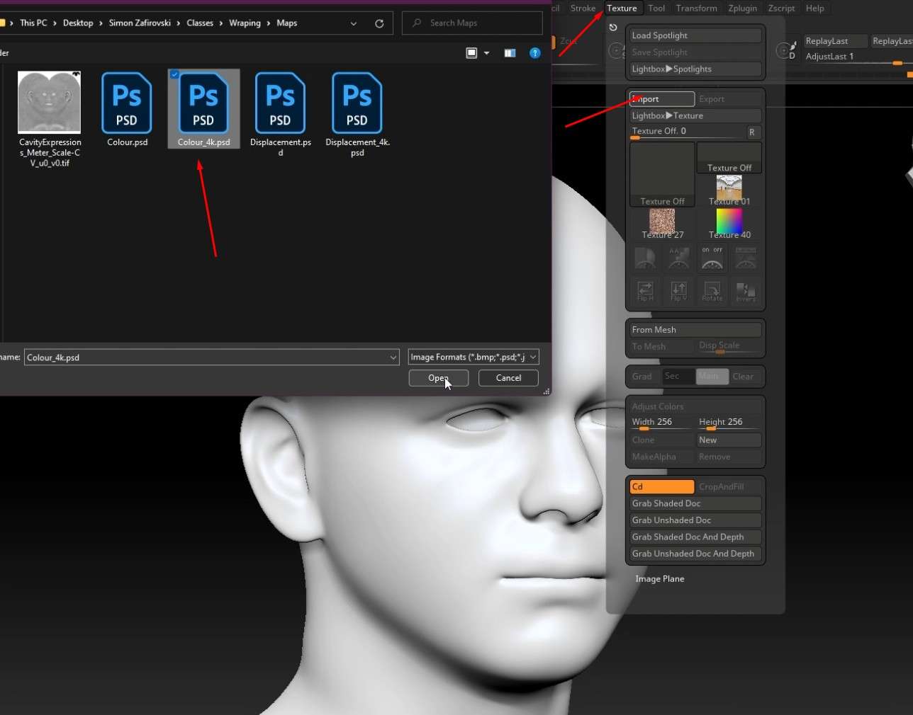
- To add textures, click the Texture tab and click on the Import button.
- Click Open after selecting the Color 4k PSD file that was provided for the class.
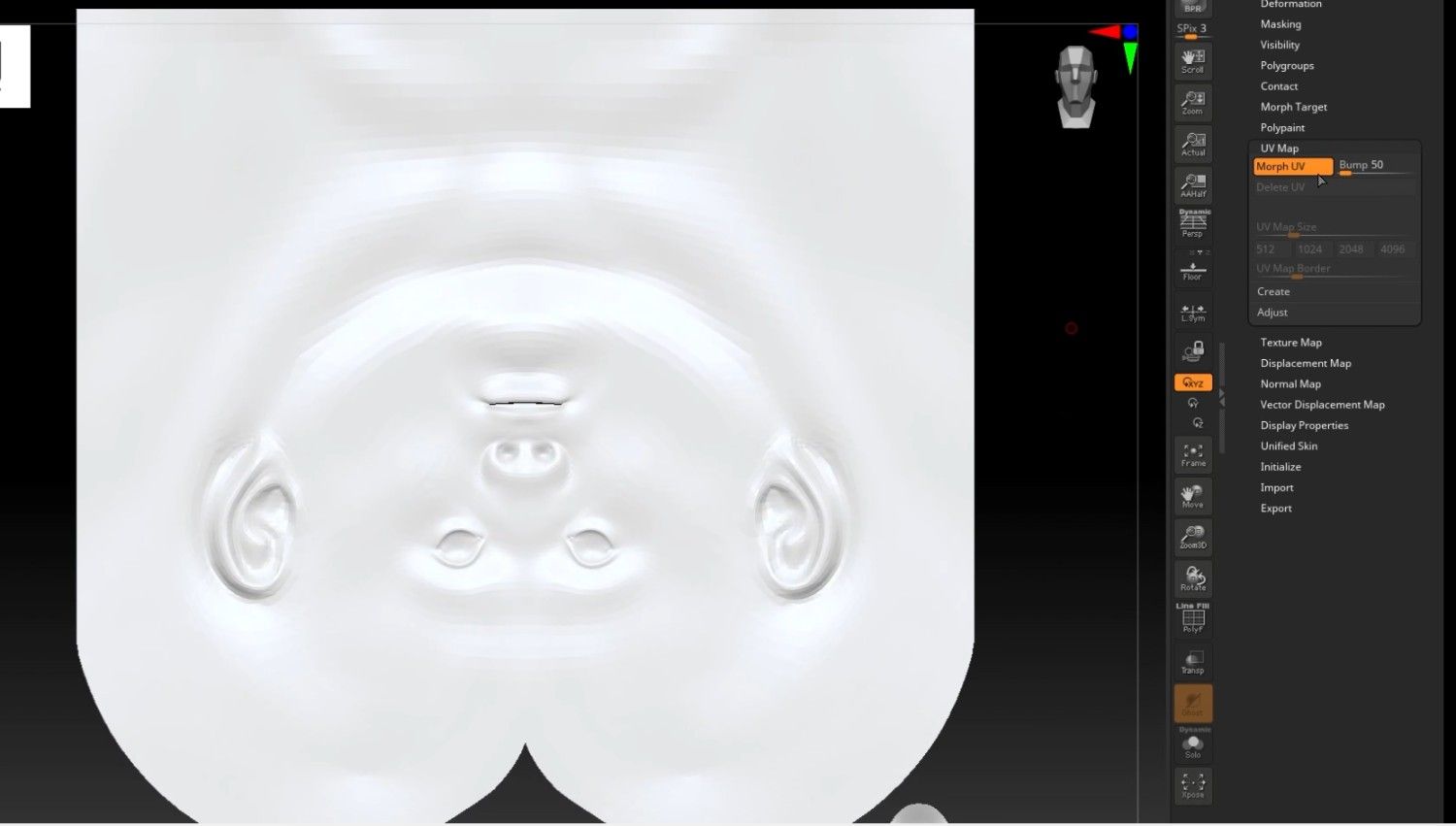
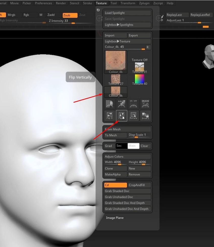
- Flip the UV map to the correct side.
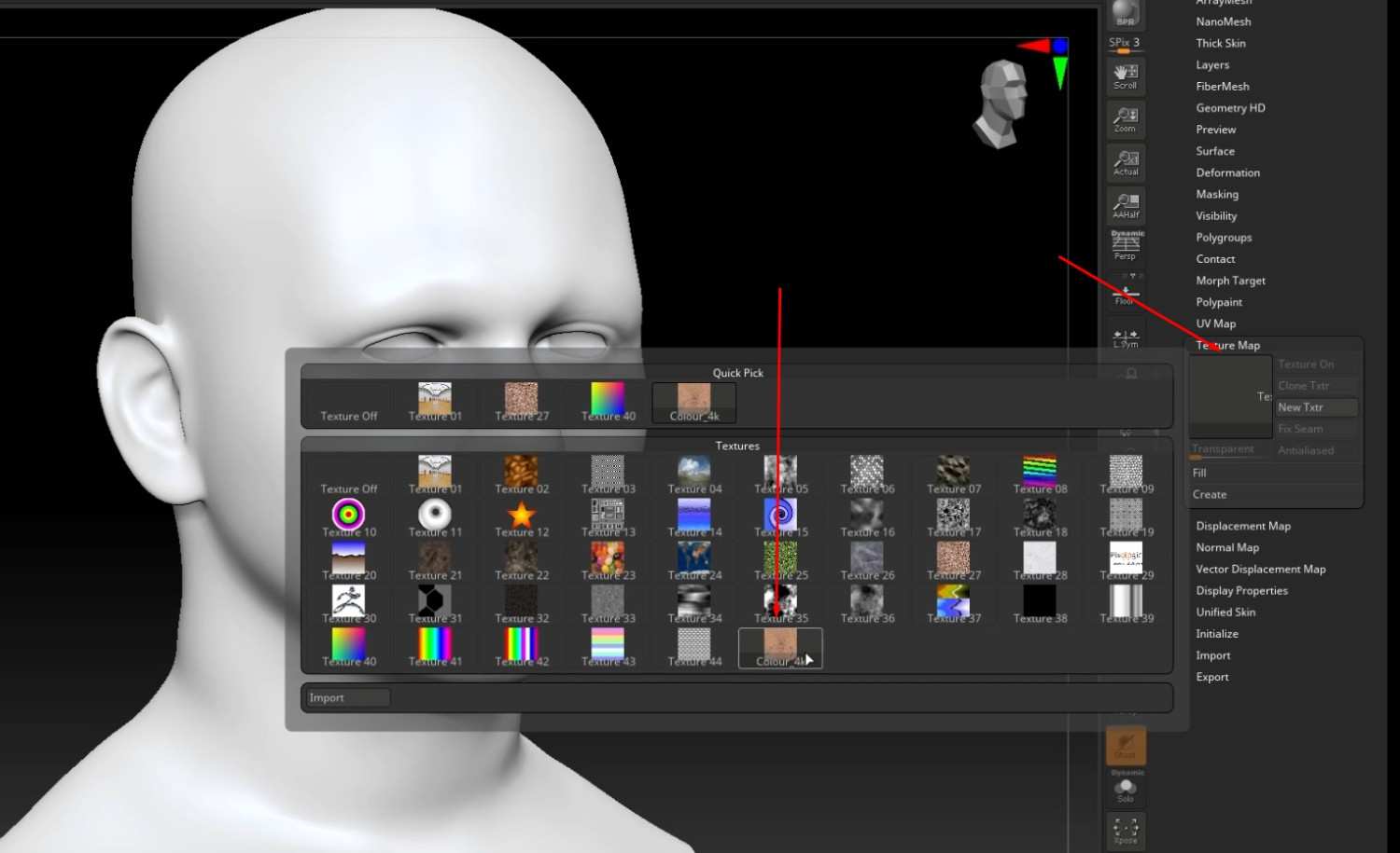
- In the Texture Map tab, click the gray box and add the Color 4k PSD file.
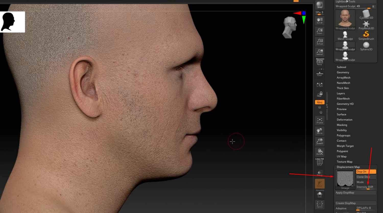
- Repeat the same steps for the Displacement map, but this time, the displacement map goes into the Displacement map tab.
- You can control the intensity of the map by lowering and raising the scale in the tab.
Bonus: Exporting Layers from ZBrush into Blendshapes
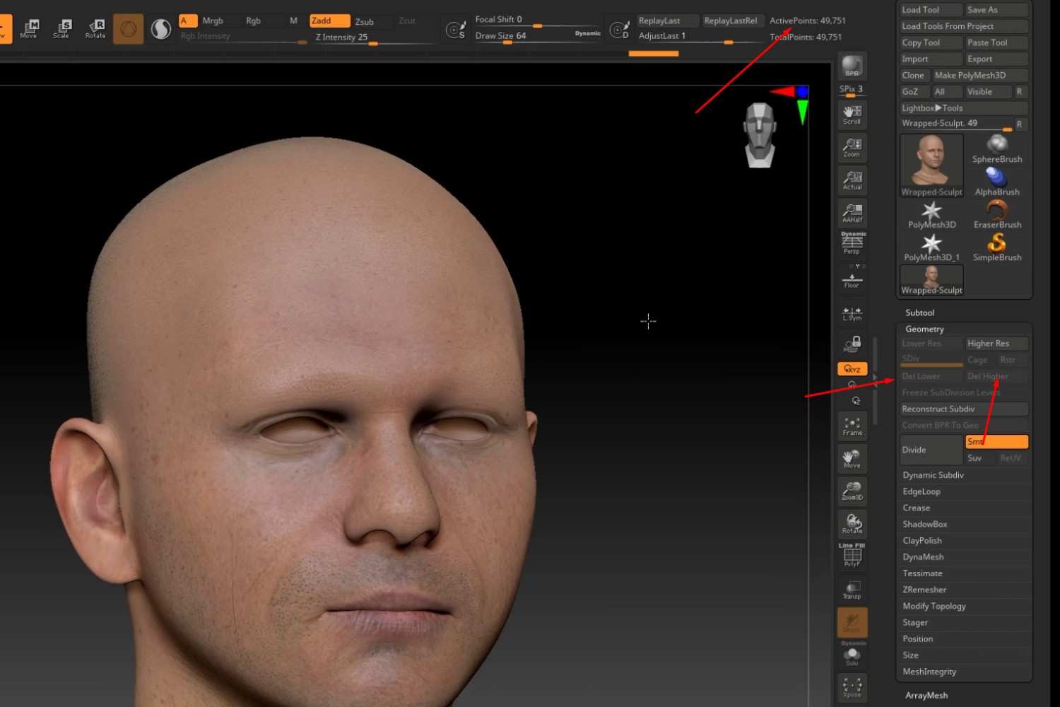
- Set the model to the 2nd division, then click Del Lowe and Del Hidden to delete the rest of the divisions.
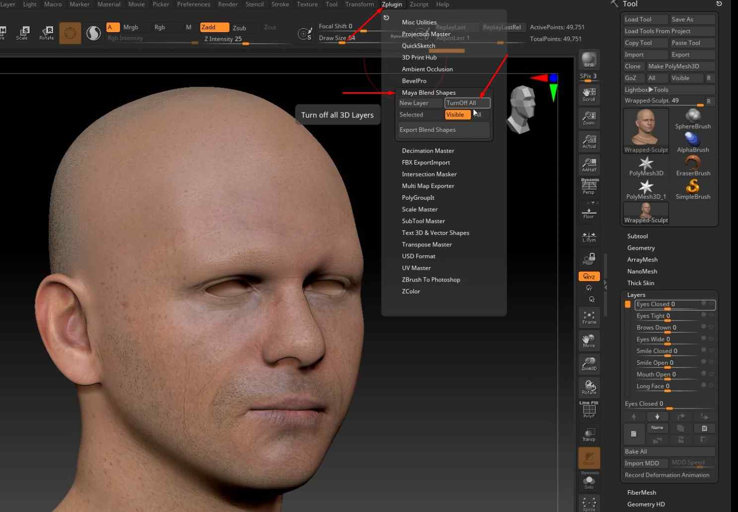
- In the Zplugin tab, open the Maya Blend Shapes sub-menu and click the TurnOff All button to turn off all the layers.
- Hold off until all of the layers have completely turned off.
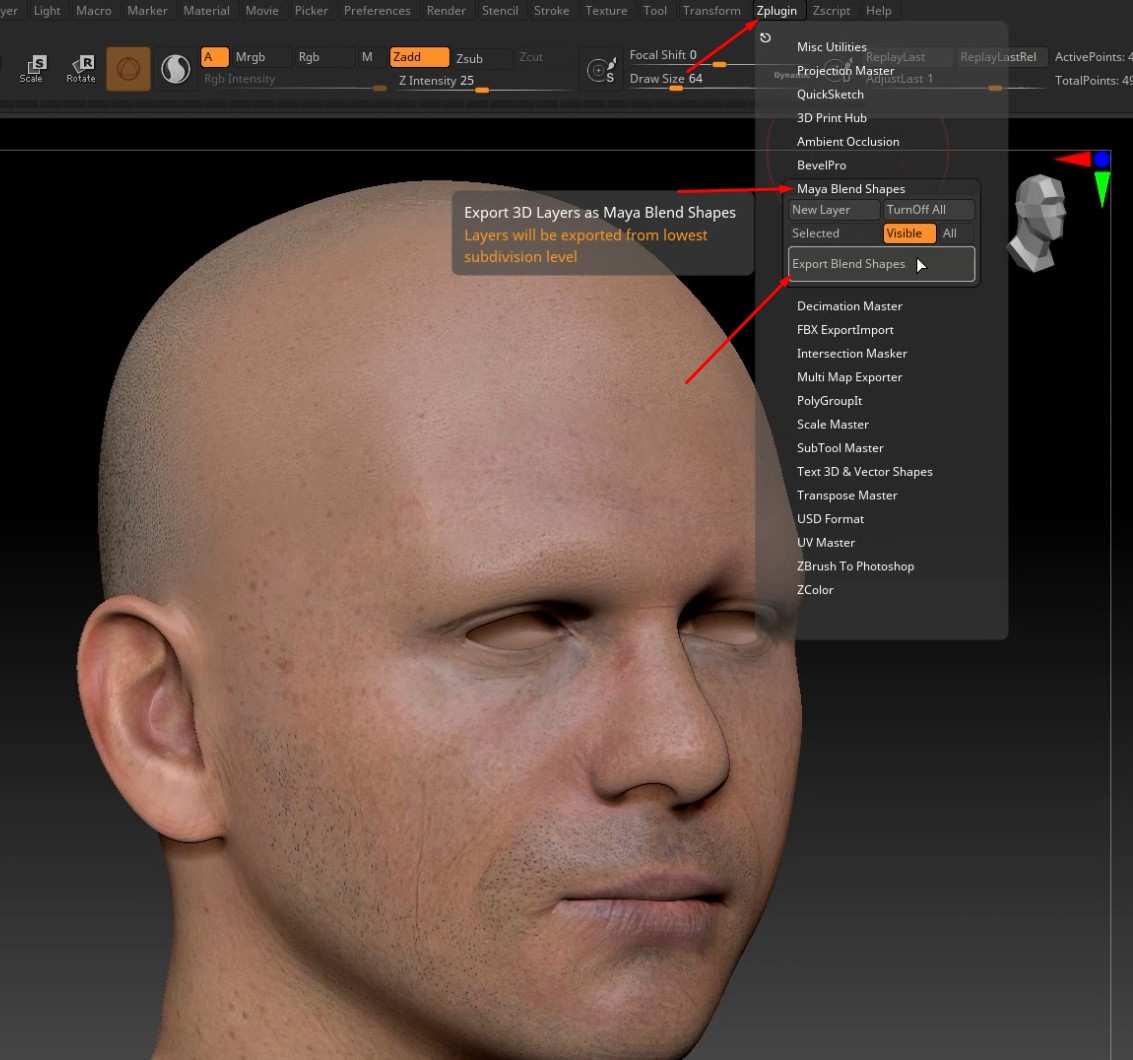
- After the layers have been turned off, open the Maya Blend Shapes sub-menu and click the Export Blend Shapes button to export everything.
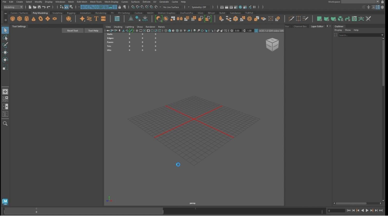
- In Autodesk Maya, import the exported file.
- It will take a while before the model loads in.
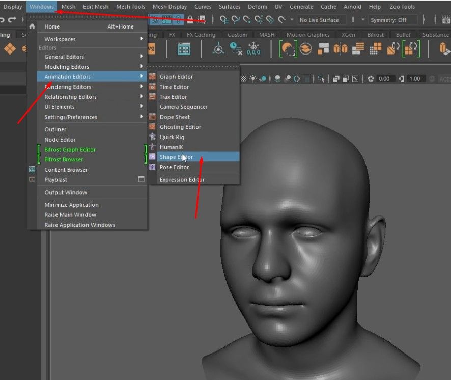
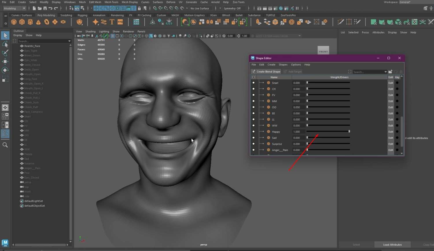
- To use the blend shapes, open the Window tab, Animation Editors, and click the Shape Editor.
- From the Shape Editor Window, you can use the blend shapes and change the expression on the model.
Conclusion: Effective Head Retopology for Game-Ready Models
By using Wrap 3D for head retopology, you can transform complex sculpts into clean game-ready models while maintaining UV maps and ZBrush details. This method improves the topology of your character and also makes it easier to apply textures, displacement maps, and blend shapes for facial expressions in Autodesk Maya. For those aiming to refine their expertise and develop a professional portfolio, M3DS Academy’s Autodesk Maya course offers hands-on experience and one-on-one mentoring tailored to the needs of aspiring 3D artists.
And don’t forget to check out what other educational approaches M3DS offers: academy programs, individual software courses, and masterclasses from industry professionals—those folks know their stuff! When ready, feel free to visit the enrollment & finance area online anytime, 24/7, because you can start your learning process immediately by becoming a top-notch creative pro.

